Having moved away from software development and design and more towards management of IT processes and services, I have found that Business Process Modelling is more applicable than UML to describing the kinds of processes I am encountering. This is not surprising, as UML is more IT-centric and I needed more flexibility to capture the realities of how things work in real life. Yes, you can use a combination of UML diagrams to capture a real-world process, but this is not as intuitive to non-IT people of which I encounter more often.
My first attempts at modelling a business process was using activity diagrams, sequence diagrams and use case models. The use case model defines all of the actors involved – both people and systems, the sequence diagram showed the message flow between them.
However, this was still too low-level and I needed something that would capture the “big picture”. After all, a high-level process (e.g. a sales process) can naturally be broken down into sub-processes. Each level of detail provides meaning to the different layers of the organization as appropriate. Of course, UML is still important for helping to formally describe the resulting IT systems implementation.
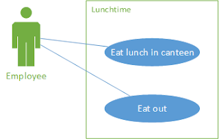
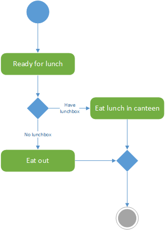
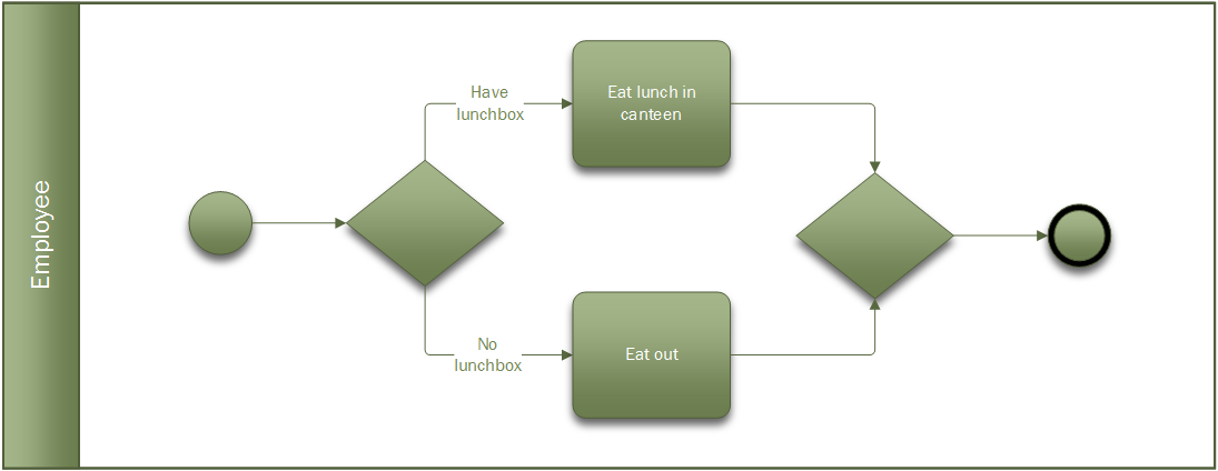
The nice thing about BPMN is that you can practice it all the time. With UML you generally want to be working on something IT related, but BPM can be applied to any process. For instance, how do people get something to eat for lunch? Do they eat out or have they brought a lunch box? This process can be described using BPMN.
If BPM interests you and you are reading this article, the chances are that you are a pioneer in in your organization. BPMN is an industry-standard notation so if you are learning BPMN then the quicker you learn the rules and follow best-practice the more rewarding will be the result. I highly recommend the following two books:
Spending time formally documenting a process may seem like a waste of time in some ways. In the real world, situations change and people adapt or take shortcuts and the process model may be out-of-date in no time, but your BPMN model should not try to capture every detail or variation. More importantly, modelling a process using BPMN is an excellent aid to understanding how a given process currently works (even if it is dysfunctional). This process analysis can be much more complete when using a comprehensive notation like BPMN – if it can’t be modelled in BPMN then there is probably some wrong assumption or something hidden in the process that needs to be investigated. BPMN gives you the confidence to pursue a process analysis to its proper conclusion.
I will finish with an example of a process model I was grappling with recently. Systems integration is often done using messaging, typical of a Service Oriented Architecture. Files are transferred from one server to another and then imported into the recipient software system. (As this is an IT-centric problem I could of course have used UML to model this.) File transfer is either push or pull, in this case push. The sender places files on the recipient’s file system. The receiver checks for new files every few seconds and if it finds any it processes them.
Modelling system interaction in BPM it is called a collaboration. The collaboration is named after the process, in the case “File transfer”, and the lanes are named after the actors. The first thing I had to figure out was whether to use events to show that a message had arrived. At the same time the recipient is busy polling the directory looking for files, and will continue to do so as long as the service is available.
The sender and receiver are modelled as two separate processes. The sender sends the file using a message activity with a message flow symbol attached.
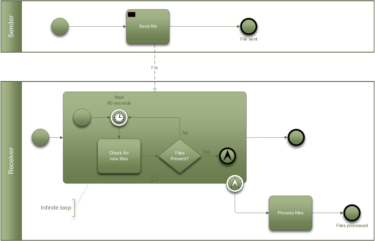
The message is sent to the recipient’s polling subprocess which can generate a non-interrupting escalation event (ooh!) (the little arrow in the dotted circle) to trigger the next activity that processes the files. The subprocess is looped (the little circular arrow), so it will continue to run after the escalation occurs (forever in this case).
So how did I know how to use a non-interrupting escalation? Well, the non-interrupting part is just saying that the event does not interrupt the subprocess flow, i.e. polling will still continue when files have been found. The escalation part, just means that the polling process has found files and needs someone else to deal with them, so it notifies the parent process (escalation).
The diagrams were produced using Visio Professional 2016 which includes a function to validate the diagram according to BPMN 2.0 (“Check diagram”).